
Lập trình modbus HMI SAMKOON ARDUINO
Hôm nay mình giới thiệu các bạn về MODBUS HMI SAMKOON
Các chế độ modbus
02 READ INPUT STATUS
03 READ HOLDING REGISTERS
04 READ INPUT REGISTERS
05 WRITE SINGLE COIL
06 WRITE SINGLE REGISTER
15 WRITE MULTIPLE COILS
16 WRITE MULTIPLE REGISTERS
địa chỉ :0000-9999 một thiết bị master có thể đọc và ghi địa chỉ này
địa chỉ :1000-19999 digital Input
địa chỉ :3000-39999 analog Input
địa chỉ :4000-49999 analog output
Để mô phỏng được modbus có thể test với phần mền hoặc phần cứng,
Phần mền HMI SAMKOON
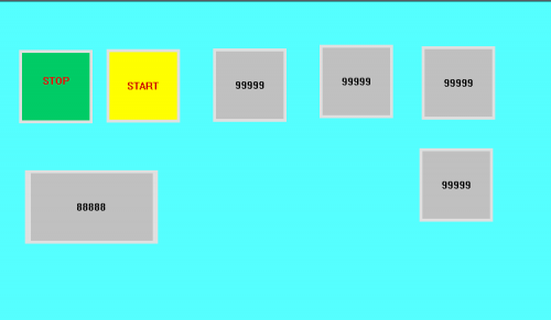
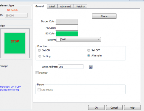
Nút STOP Đặt địa chỉ 0x01
Tương tự nút START địa chỉ 0x02
Đến mục hiển thị số
30001-39999 Analog Inputs,
Thanh ghi chỉ ghi được và không đọc được ,để hiển thị các biến ADC ,PWM
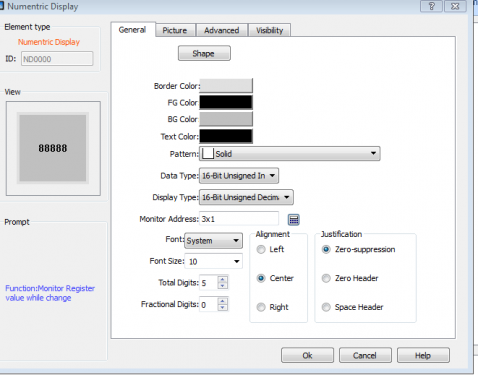
Tiếp tục Đến 40001-49999
Thanh ghi có thể ghi và đọc được để nhập các giá trị từ 40001-49999 Analog Outputs
Chuyển chế độ online kết nối HMI Qua cổng COM PORT
CODE ARDUINO
#include <ModbusRtu.h>
long int cnt_modbus=0;
long int bit_modbus;
#define ID 1
Modbus slave(ID, 1, 1); // this is slave ID and RS-232 or USB-FTDI
boolean led;
int8_t state = 0;
unsigned long tempus;
// data array for modbus network sharing
uint16_t au16data[6];
uint8_t u8id;
uint8_t u8fct;
uint16_t u16RegAdd;
uint16_t u16CoilsNo;
uint16_t * au16reg;
/**
* Setup procedure
*/
void setup() {
io_setup(); // I/O settings
Serial.begin(9600);
// start communication
slave.begin( 9600);
tempus = millis() + 100;
digitalWrite(13, HIGH );
}
/**
* Loop procedure
*/
void loop() {
// poll messages
// blink led pin on each valid message
state = slave.poll( au16data,400);
if (state > 4) {
tempus = millis() + 50;
digitalWrite(13, HIGH);
}
if (millis() > tempus) digitalWrite(13, LOW );
// link the Arduino pins to the Modbus array
io_poll();
}
/**
* pin maping:
* 2 – digital input
* 3 – digital input
* 4 – digital input
* 5 – digital input
* 6 – digital output
* 7 – digital output
* 8 – digital output
* 9 – digital output
* 10 – analog output
* 11 – analog output
* 14 – analog input
* 15 – analog input
*
* pin 13 is reserved to show a successful query
*/
void io_setup() {
// define i/o
pinMode(2, INPUT);
pinMode(3, INPUT);
pinMode(4, INPUT);
pinMode(5, INPUT);
pinMode(6, OUTPUT);
pinMode(7, OUTPUT);
pinMode(8, OUTPUT);
pinMode(9, OUTPUT);
pinMode(10, OUTPUT);
pinMode(11, OUTPUT);
pinMode(13, OUTPUT);
digitalWrite(6, LOW );
digitalWrite(7, LOW );
digitalWrite(8, LOW );
digitalWrite(9, LOW );
digitalWrite(13, HIGH ); // this is for the UNO led pin
analogWrite(10, 0 );
analogWrite(11, 0 );
}
/**
* Link between the Arduino pins and the Modbus array
*/
void io_poll() {
// get digital inputs -> au16data[0]
//Serial.println( au16data[0]);
// bitWrite( au16data[0], 0, digitalRead( 2 ));
// bitWrite( au16data[0], 1, digitalRead( 3 ));
// bitWrite( au16data[0], 2, digitalRead( 4 ));
// bitWrite( au16data[0], 3, digitalRead( 5 ));
// set digital outputs -> au16data[1]
// digitalWrite( 6, bitRead( au16data[1], 0 ));
// digitalWrite( 7, bitRead( au16data[1], 1 ));
// digitalWrite( 8, bitRead( au16data[1], 2 ));
// digitalWrite( 9, bitRead( au16data[1], 3 ));
// set analog outputs
// analogWrite( 10, au16data[2] );
// analogWrite( 11, au16data[3] );
// read analog inputs
//au16data[4] = analogRead( 0 );
// au16data[5] = analogRead( 1 );
// diagnose communication
// au16data[2] = slave.getInCnt();
//au16data[1] = slave.getInCnt();
if(++ cnt_modbus>65535)cnt_modbus=0;
au16data[3]=cnt_modbus;
au16data[2]=cnt_modbus;
// au16data[1]=cnt_modbus;
// au16data[0]=cnt_modbus;
// Serial.println( cnt_modbus);
// au16data[8] = slave.getErrCnt();
}